
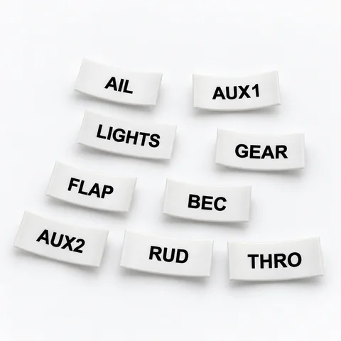
RC Servo Lead Heat-Shrink Labels
Thirty heat-shrink labels so every lead says what it is at the receiver.
$19.99 Standard 30-Pack
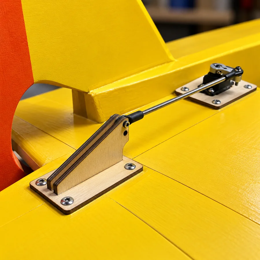
Laser-Cut Control Horn + Servo Mount System for Large RC Aircraft
A complete heavy-duty linkage solution for large scratch-built RC aircraft, based on the control system developed for our 20-foot RC airplane.
2 Pack two complete linkage sets
$29.99 per kit · $15.00 per linkage set
The 4-Pack is $4.99 less than two 2-Packs.
Build the linkage. Mount it. Fly it.
Heavy-duty control hardware developed for giant RC aircraft.

When you’re building a large RC airplane, the usual lightweight plastic control horn can quickly become the weak link in the system.
This kit gives scratch builders a larger, more substantial control linkage setup using laser-cut plywood components, a threaded linkage, and a dedicated servo mounting base.
It was originally developed while building a 20-foot RC airplane, where the size of the control surfaces demanded something much larger than typical small-aircraft hardware.
Developed on a 20-foot RC airplane
Instead of sourcing each piece independently and figuring out the geometry from scratch, the kit gives builders the core parts needed to create a straightforward heavy-duty control linkage.
Not included: servo, servo arm, adhesive, and airframe mounting hardware. The screws that fix the horn base and the servo plate to your airframe depend on what the airframe is made of, so they are yours to choose. Aircraft and adhesives shown in installation photos are not included; the photos show the kit installed.
Showing the 2-Pack. Change pack ↑
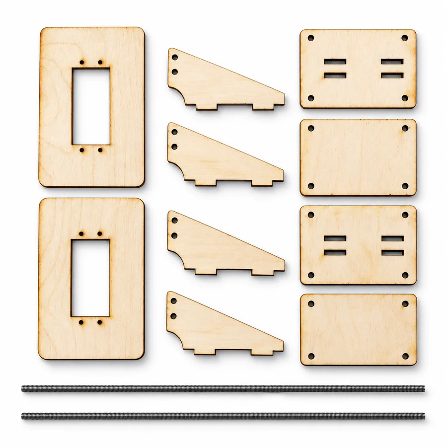
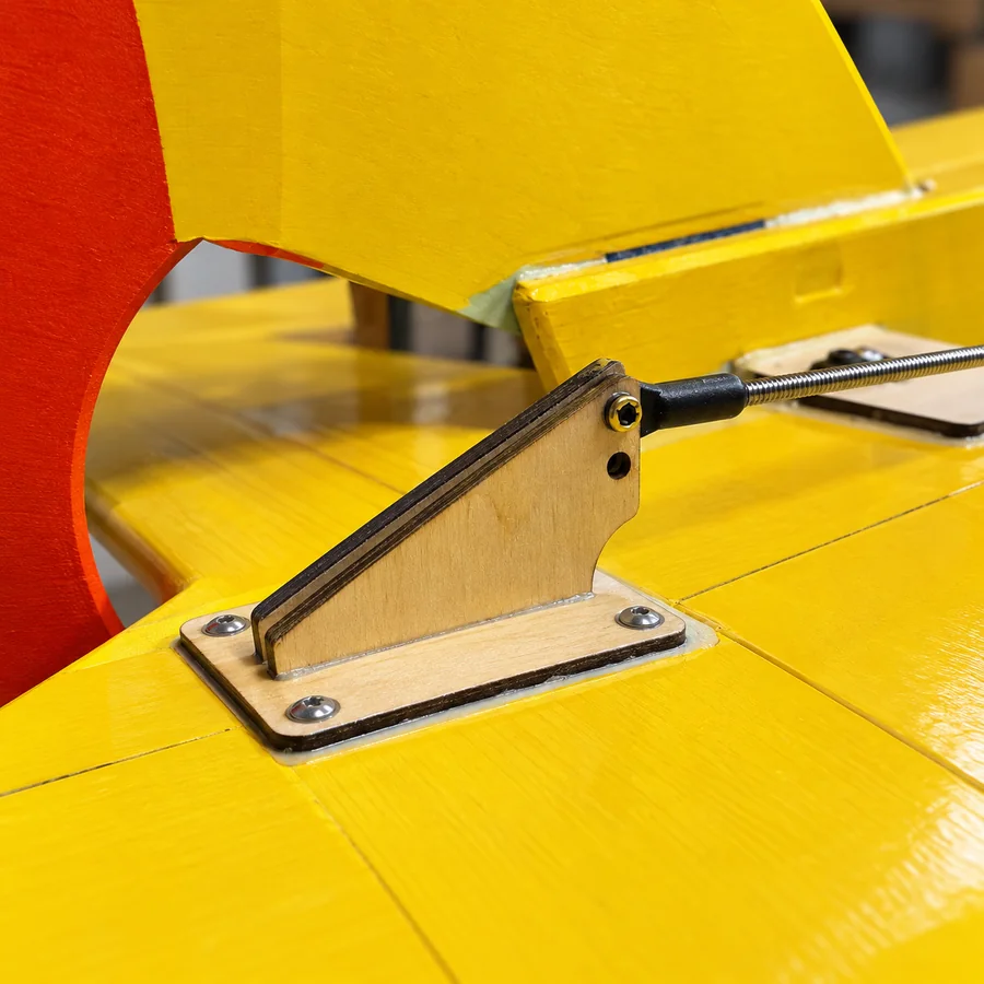
The dual-plate control horn design spreads the linkage connection across a larger structure than a small single plastic horn and gives large scratch-built aircraft a sturdy mounting point for the pushrod.
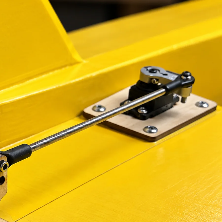
Large scratch-built airplanes rarely give you a convenient factory servo pocket. The included mounting plate gives you a simple base that can be bonded or mechanically integrated into your airframe.
Screw the servo to the plate, then fix the plate to the structure, so the servo load goes into a plywood plate rather than into foam. Check the plate against your servo before ordering; exact plate dimensions will be listed below once confirmed.
This linkage wasn’t designed as a theoretical product. It started as hardware for a giant 20-foot RC airplane project. Standard control hardware didn’t make much sense at that scale, so a larger plywood control horn and dedicated servo mounting system were built instead.
After using the design on the aircraft, the same concept was turned into a kit so other RC builders could use it on their own large custom airplanes.
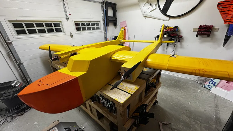
Designed with large custom RC aircraft in mind. No size, weight or load rating is quoted, because the right answer depends on your airplane; see the engineering note below.
The linkage pivot should be positioned appropriately relative to the control-surface hinge line.
The exact attachment method depends on the airframe construction: screws into a hard point, or bonded, with the structure under it reinforced.
Place the servo so that the linkage runs as straight as reasonably possible through its range of motion.
Set the threaded linkage length, verify servo travel, and make sure the linkage operates smoothly without binding.
Before flight: always verify linkage geometry, full servo travel, control direction, mechanical clearance, fastener security, and structural integrity.
| Kit quantity | 2 complete linkage sets (2-Pack) or 4 (4-Pack) |
|---|---|
| Control horn | Laser-cut plywood, two plates on a base plate, two linkage holes |
| Servo plate | Laser-cut plywood |
| Linkage | Threaded pushrod, adjustable on the thread, with a swivel linkage end at each end |
| Included hardware | What connects the pushrods to the control horns and servo arms |
| Not included | Servo, servo arm, adhesive, airframe mounting hardware |
| Servo | Not included; check your servo against the plate |
| Intended use | Large scratch-built and custom RC aircraft |
| Developed on | Eric’s 20-foot RC airplane |
Only what has been confirmed is listed. Plywood thickness, plate and horn dimensions, rod diameter and length, thread size, fastener sizes and kit weight will be added here once measured on the production kit; none is quoted until then. Need one now? Ask before you order.
This is intended as builder hardware rather than a model-specific replacement part. You decide where the servo, horn, and linkage are installed in your airframe.
That makes it useful for custom aircraft, but it also means the builder is responsible for choosing appropriate mounting locations, linkage geometry, adhesives, fasteners, servo torque, and structural reinforcement.
This kit is intended for experienced RC hobby use. Aircraft loads vary dramatically depending on aircraft size, speed, control-surface area, servo torque, linkage geometry, construction method, and flight conditions.
The builder is responsible for determining whether the components and installation are appropriate for the aircraft. Inspect all control hardware before every flight. The kit is not certified, load-rated or fail-safe; no formal testing supports such claims and none is made.
The small parts I use on every build, sold here too. Each is added to the cart on its own.
Thirty heat-shrink labels so every lead says what it is at the receiver.
$19.99 Standard 30-Pack
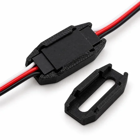
Fifty locks that fit around a joined servo connection so the long extensions on a big airplane stay plugged in.
$14.99 50-Pack
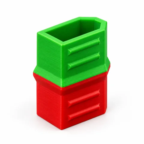
Green end out means charged, red end out means flown. Twelve caps for the whole battery box.
$11.99 12-Pack
Something else? Ask Eric — the answer gets added here if it would help the next builder.